Additive Manufacturing (AM) & Powder Bed Fusion (PBD)
Additive Manufacturing
Unlike the conventional manufacturing processes which involve casting from a mold to make a product, additive manufacturing (AM) can directly produce 3D complex components using CAD (computer-aid design) data. Therefore, AM has grown rapidly over the past few years and is now one of the most widely used technologies worldwide. If you are not familiar with the term additive manufacturing, allow me to introduce the other name of it - 3D printing.
Compared to Convention Manufacturing
Conventional manufacturing, such as under computer numerical control, needs to select suitable tools and materials for specific products. It also needs to create reasonable routes for the computer to run in order to prevent tool crush. What's more, detailed plans should be created to make complicated products.
In short, conventional manufacturing is complicated and inflexible for producing customized and intricated products. In contrast, AM is a tool-free manufacturing method. There’re nearly no limits for AM because it’s a layer-by-layer producing strategy, like building blocks. AM can easily make customized and personalized components and play a conspicuous role in the artificial joint and dental area.
General Process of Additive Manufacturing
The core idea for additive manufacturing is by adding materials level-by-level. And its whole process is controlled by CAD data. AM uses a heat source such as a laser, electron beam, or ultraviolet light (UV) to melt metals to spray layers. The layer thickness is a significant factor that can affect the speed of AM. The thinner the layer thickness, the more detailed and delicate components we make, and at the same time, the more time AM needs. This is a brief summary of the additive manufacturing process. Let’s now get more detailed information about it.
Step 1
The first step is to build up a 3D model by using CAD software. We can also scan the finished sample to build a copy 3D model reversely. The main goal is to make the geometric digital part for the following printing.
Step 2
Then, convert CAD data into STL (standard tessellation language) format. This format type only represents the surface geometry for a 3D subject, but can't show the colors, materials, or other properties from CAD data. STL format can sometimes be replaced by AMF (additive manufacturing file).
Step 3
Since AM produces materials layer-by-layer, STL data need to be “dismantled” into pieces. Then, we need to convert these pieces into codes that the AM system can use. Usually, the generated toolpath will be converted into G-code format. These are the all pre-preparation for AM setup.
Steps 4
After pre-reparation, the AM machine must be properly operated to avoid producing defective goods. The final stage of a product can be impacted by factors like material type, layer thickness, power supply, moving speed, environment temperature, and more. Additionally, as AM is a layer-by-layer printing method, support must be platen when printing piercing, or suspending components. Additionally, the plate support can be removed directly or separated using various solvents. After these considerations, the last thing which needs to be careful is to make sure AM machine has enough supporting materials to work.
Step 5
When the printing process is finished, some products can be easily removed from the plate, while some may need burning or using chemical solvents to dissolve the useless parts to remain the target part.
Some products for specific applications need to take other processes to meet the requirements of the product before use. For example, some need to be heated to improve the specific properties of the product, and some may need to be polished to meet its smoothness requirements.
Powder Bed Fusion
Additive manufacturing has several divisions: powder bed fusion, directed energy deposition, binder jetting, material jetting, material extrusion, vat photopolymerization, and sheet lamination [1]. We will focus on laser-powder bed fusion.
What is Powder Bed Fusion?
Powder bed fusion uses laser or electron beams as the heating source to fuse selective areas of powder particles layer-by-layer to create unique complicated products. Laser-Powder bed fusion (L-PBF) has different names in science and literature such as selective laser melting (SLM), direct metal laser sintering (DMLS), LaserCusing, etc.[2]L-PBF is a technology constituted by lots of subprocesses: “the absorption and reflection of laser radiation by a dispersed medium, heat and mass transfer, phase transformations, a moving interface between phases, gas and fluid dynamics, chemical reactions, solidification and evaporation, shrinkage, deformation, etc. [2]”
More than 130 input parameters can influence the L-PBF process. The most important influencing factors are “Machine based’, “Material based”, “Process parameters” and “Post-treatment parameters”. In fact, unlike control variate experiments a small change in L-PBF can’t directly show a very direct change in output. Usually, a small change can lead to many corresponding changes which may cause unpredictable results. PBF still needs more study to be a comprehensive technology. Figure 1 [1] shows the L-PBF’s general process.
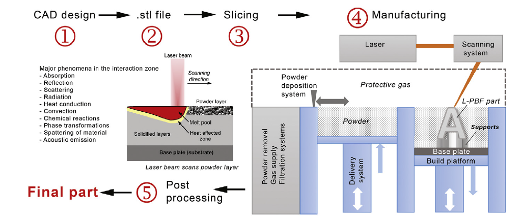
Figure 1: L-PBF working process [3]
L-PBF’s main procedures
A roller/recoater takes the powder (usually metal or polymer spherical powder such as spherical titanium powder) from the delivery system and spreads an even thin layer on the base plate. Then, the laser beam from the scanning system fuses the powder on the base plate with the control of the computer. A thin layer is produced and then the build platform will move down by a layer’s distance and the delivery system will move up by a layer’s distance to continue the repeated steps. After all, it takes post-processing: take products from the powder and remove the powder on the products. All these procedures take place under a protective gas atmosphere to protect the powder from reacting with O2.
Micro view in L-PBF
Two tiny particles melt and fuse together by the force of their surface tension when the laser beam fuses the powder (in this case, we only discuss liquid-phase sintering). “Viscous flow is the main driving force during this process,” said Sahoo [4]. And the coalescence is named the neck formation. A more detailed explanation of the entire procedure is shown in Figure 2 [4].
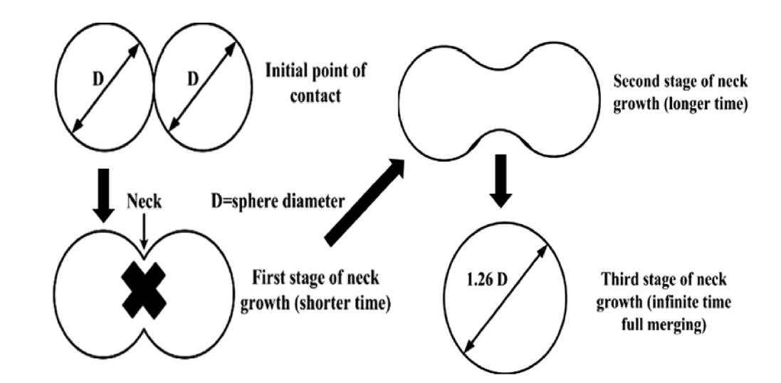
Figure 2: Coalescence process
In the beginning, two particles touch together. When temperature increases, they start to melt and join to the neck forms due to their high surface energy. This process is called surface diffusion. The length of the neck keeps increasing till surface diffusion ends. At this time, the neck length reaches its maximum value. The grain boundary diffusion takes place to materialize the pores. At last, the shrinkage stops the whole process and the sintering completes.
Increasing laser beam power will cause a temperature increase. Additionally, since the grain boundary diffusion will be more stable at higher temperatures, the entire procedure may go more smoothly. As a result, the consolidation time can be reduced.
L-PBD delivery and deposition system
There’re two ways for the L-PBD delivery system. One is powder stored in the reservoir (see Figure 1) and supported by a piston moving up and down to provide powder for additive manufacturing. This is how most commercial L-PBD machines deliver their products. Another way is that the reservoir supplies powder into the hopper. The hopper locates above the working plane to provide the powder. This’s a combination of delivery and deposition systems. [5]
After delivery, the deposition system mainly supports the thin and uniform layer of powder for the laser beam to fuse. Most powder deposition system takes linear reciprocating movements. The recoating system has many types such as soft blade recoater (silicon or rubber blade), hard blade recoater (hard tool steel), and roller (hard tool steel).
Soft blade recoater is soft and flexible and it will not damage the part. What's more, it offers advantages for making delicate, readily broken, or distorted cellular structures. However, the soft blade recoater is relatively weaker and is often needed to be exchanged.
Hard blade recoater, unlike soft blade recoater, doesn’t allow any deformation of the metal during manufacturing. It will stop and the defective part will not be produced. So it saves both time and money.
Roller can spread the powder in a 3D system and make a very well-leveled powder layer. The roller can be utilized in tiny working fields to create smaller particles by taking into account how it operates.
Powder material
One of the most essential components in the L-PBF process is the powder material. It can affect the further parameters for the machine to set up. Additionally, the powder material largely determines the qualities of products.
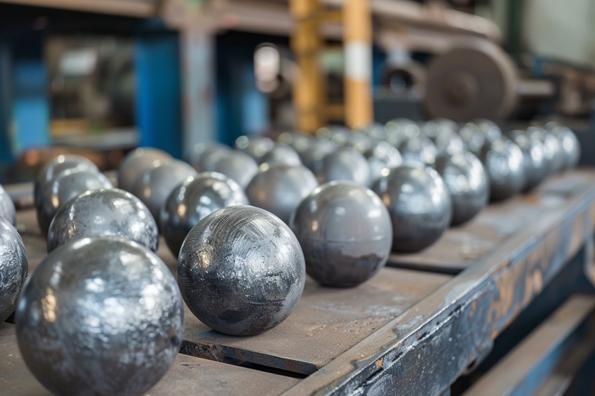
L-PBF systems use metal powder ranging from 5 to 60 μm. The most suitable powders for L-PBF are spherical powder which has a high packing density, good flowability, and can even spread to the substrates [5]. For example, Spherical Nickel Powder, FeAlNiCrX High-Entropy Alloys Powder, Spherical Cobalt-Based Powder, and so on are the main popular spherical powders used in the L-PBF area.
Reference:
- Yadroitsev, I., Yadroitsava, I., Plessis, A. D., & MacDonald, E. (2022). 2 - Basics of laser powder bed fusion. In Fundamentals of laser powder bed fusion of metals (pp. 16). essay, Elsevier.
- Yadroitsev, I., Yadroitsava, I., Plessis, A. D., & MacDonald, E. (2022). 2 - Basics of laser powder bed fusion. In Fundamentals of laser powder bed fusion of metals (pp. 18). essay, Elsevier.
- Yadroitsev, I., Yadroitsava, I., Plessis, A. D., & MacDonald, E. (2022). 2 - Basics of laser powder bed fusion. In Fundamentals of laser powder bed fusion of metals (pp. 19). essay, Elsevier.
- Sahoo, S. (2020). Consolidation behavior of metal powders in laser additive manufacturing. Metal Powder Report. https://doi.org/10.1016/j.mprp.2020.06.060
- Yadroitsev, I., Yadroitsava, I., Plessis, A. D., & MacDonald, E. (2022). 2 - Basics of laser powder bed fusion. In Fundamentals of laser powder bed fusion of metals (pp. 26-30). essay, Elsevier.