Positive or Negative? A Beginner's Guide to Thermocouple Wire Identification
Thermocouples are indispensable tools in the measurement of temperature, extensively used across various industries such as manufacturing, food processing, and aerospace. At the heart of a thermocouple's functionality is its ability to convert thermal energy into electrical energy, a process that hinges on two dissimilar metals joined at one end.
As straightforward as it sounds, the correct identification of thermocouple wires—distinguishing between the positive and negative—is critical for accurate temperature measurement. This beginner's guide will demystify the process of thermocouple wire identification, ensuring you can confidently navigate this fundamental aspect of thermocouple use.
What are the positive and negative on thermocouple wire?
The key to correctly identifying thermocouple wires lies in understanding the color coding system. While it may vary by country and thermocouple type, a general rule applies: one wire is positive, and the other is negative.
Identifying a thermocouple by its wire color coding system is an essential skill for accurately setting up and troubleshooting thermocouple temperature measurement systems. Different types of thermocouples use different metal combinations, and each type has a designated color code to help users identify them correctly. Here’s a straightforward guide on how to identify a thermocouple by its wire color coding, primarily following the American National Standards Institute (ANSI) standards, which are widely used in the United States.
1. Know the Types of Thermocouples
First, it's important to familiarize yourself with the different types of thermocouples. Each type is designated by a letter (e.g., K, J, T, E) and has specific applications based on its temperature range and sensitivity. The most common types are:
Type K: Nickel-Chromium / Nickel-Alumel
Type T: Copper / Constantan
Type E: Nickel-Chromium / Constantan
2. How to Identify a Thermocouple by Wire Color Coding System?
In the United States, the ANSI (American National Standards Institute) standard is widely followed. According to this standard, the wire color corresponds to the thermocouple type.
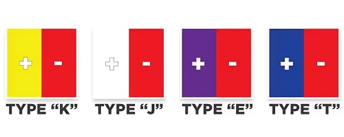
The ANSI standard assigns specific colors to the insulation of thermocouple wires. This system helps in identifying both the type of thermocouple and which wire is positive and which is negative. Here's how to identify some of the most common types:
Type K: The positive wire is yellow, and the negative wire is red.
Type J: The positive wire is white, and the negative wire is red.
Type T: The positive wire is blue, and the negative wire is red.
Type E: The positive wire is purple, and the negative wire is red.
We focus on the ANSI and IEC color codes for thermocouples, their wire and connectors, alloy combinations, maximum temperature range, and specific codes. Here's the updated table:
|
ANSI Code |
ANSI MC 96.1 Color Coding |
Alloy Combination |
Max Temp. Range |
IEC 584-3 Color Coding |
IEC Code |
|
Type K |
Yellow (+) / Red (−) |
Ni-Cr / Ni-Al |
-270°C to 1372°C |
Green (+) / White (−) |
KX |
|
Type J |
White (+) / Red (−) |
Fe / Cu-Ni |
-210°C to 1200°C |
Black (+) / White (−) |
JX |
|
Type T |
Blue (+) / Red (−) |
Cu / Cu-Ni |
-270°C to 400°C |
Brown (+) / White (−) |
TX |
|
Type E |
Purple (+) / Red (−) |
Ni-Cr / Cu-Ni |
-270°C to 1000°C |
Purple (+) / White (−) |
EX |
|
Type N |
Orange (+) / Red (−) |
Ni-Cr-Si / Ni-Si |
-270°C to 1300°C |
Rose (+) / White (−) |
NX |
Key Components of the Table:
- ANSI Code: Designates the thermocouple type according to the American National Standards Institute.
- ANSI MC 96.1 Color Coding: Shows the color coding for thermocouple and extension grade wires as per ANSI standards. The color for the positive lead is listed first, followed by the negative lead.
- Alloy Combination: Indicates the metals used in the positive (+) and negative (−) leads for each thermocouple type.
- Max Temp. Range: Specifies the temperature range within which the thermocouple type can accurately measure.
- IEC 584-3 Color Coding: Lists the color coding for thermocouple grade wires according to the International Electrotechnical Commission standards, with the positive lead color mentioned first.
- IEC Code: The designation for the type of thermocouple according to IEC standards, with "X" indicating extension grade.
This streamlined table provides essential information for identifying thermocouples by their ANSI and IEC color codes, highlighting differences in coding systems between American (ANSI) and International (IEC) standards.
3. Check the Overall Insulation Jacket
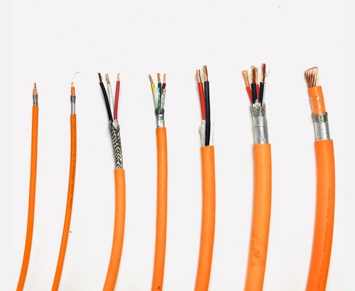
In addition to the individual wire colors, the overall insulation (the outer jacket) of the thermocouple cable also follows a color code that corresponds to the type of thermocouple. This can provide an immediate visual cue to the type of thermocouple you are dealing with:
Type K: Yellow jacket
Type J: Black or white jacket
Type T: Blue jacket
Type E: Purple jacket
4. Inspect for International Standards
Be aware that the color coding system can vary in different countries. For example, in Europe and other parts of the world, the color coding system under the International Electrotechnical Commission (IEC) standards might be used, which can differ from the ANSI standards. For instance, a Type K thermocouple under IEC standards has a green positive wire and a white negative wire.
5. What to Do if Color Codes are Not Visible
If the color codes are faded or not visible, you can use a multimeter to check the resistance of the wires. Different metals will have different resistances, which can help you deduce the type of thermocouple. However, this method requires some knowledge about the resistance characteristics of the metals used in thermocouples.
6. Consult Documentation
Whenever possible, consult the thermocouple's documentation or the manufacturer's guidelines. This is the most reliable way to ensure you're correctly identifying the thermocouple, especially in critical applications.
How to Identify a Thermocouple by Wire Color Without Color Codes?
In cases where the color code is not visible or has faded, other methods may be employed:
Resistance Measurement: Measuring the resistance across the thermocouple wires can sometimes help identify them, as one type of metal may have a distinctly different resistance than the other.
Consultation with Manufacturers: When in doubt, consulting the thermocouple's manufacturer or documentation can provide the most accurate information for wire identification.
Best Practices for Thermocouple Use
To ensure accurate temperature measurements, here are some best practices to follow:
Proper Installation: Ensure that the thermocouple is correctly installed, with the positive and negative wires connected to the appropriate terminals.
Regular Calibration: Thermocouples should be calibrated regularly to maintain accuracy.
Avoid Mixing Types: Do not mix wires from different types of thermocouples, as this can lead to inaccurate readings.
Conclusion
Identifying thermocouple wires might seem daunting to beginners, but understanding the basics of thermocouple operation, the types available, and the color coding system can demystify the process. By adhering to best practices and consulting resources or professionals when in doubt, you can ensure accurate and reliable temperature measurements in your applications. Remember, in the world of thermocouples, knowing your positives and negatives is more than just an expression—it's the key to precision.